
TP-Link Smart Plug IoT Button v0
So my office lamp is in an awkward location behind a sofa. Instead of re-arranging my office furniture like a sensible person, I decided instead to just install one of those cute $20 tp-link plug that let you toggle stuff via a smart app. Of course, it turns out that the smart app takes an eon to load and I only have my phone on me about half the time.
So the answer of course, instead of re-arranging my office furniture, was to dig through the spare parts bin and make a physical button for my now smart lamp. I chose a particle photon since it speaks UDP (and has a nifty control panel, and I had one.) However, unlike the fancy new models from Particle, this doesn’t have any support for a lithium polymer (lipo) battery so we’re going to use a tp4056 package from Amazon to give us the ability to recharge our LiPo and not draw too much current from it at once. We’ll also need a button.. since that’s kind of the whole bit of this.
Parts List
- Particle Photon
- tp4056 with over-current protection
- momentary push button of your choice
- project enclosure
- female headers for mounting our Photon non-permanently
- perfboard to attach everything to
- various m2 screws and standoffs
- odd bits of cable, some jst connectors
Tools
- Soldering iron and solder
- Drill (hand drill is fine)
- A small file for fitting
- Breadboard for testing
The test bench
Let’s get out a breadboard, pop in our Photon and some sweet sweet voltage. We’re going to connect our button between D0 and our ground. We’ll also need our handy lamp that’s plugged into our smart plug.
Code
I found the protocol for talking to the smart plug from Martin Smaha’s writeup which was based on earlier work from SoftCheck.
Unfortunately the original code didn’t get the current status of the plug and was written in c++. I prefer all my code to be in the same language, so I ported what I needed to wiring, wrote some code to get the plug status (with retries and timeouts) and hooked up several of the code functions to the cloud so you can extend your smart lamp control. You’ll need to customize the device IP as appropriate for your device.
As usual with Particle devices, flashing code is as easy as setting up your device, visiting build.particle.io, pasting in the code and clicking the flash button.
// This #include statement was automatically added by the Particle IDE.
#include <ArduinoJson.h>

int debounceDelayMS = 500;
uint8_t deviceIP[4] = {192, 168, 1, 170};
int state = 0;
int buttonPin = D0;
char Buffer[1024];
UDP Udp;
SerialLogHandler logHandler;

int msBetweenSync = 1000 * 60;
unsigned long lastSync = millis();

void setup() {
    pinMode(buttonPin, INPUT_PULLUP);
    Particle.variable("debounceMS", debounceDelayMS);
    Particle.variable("ip", deviceIP);
    Particle.variable("syncMS", msBetweenSync);
    Particle.function("toggle", toggleStateFromCloud);
    Log.info("System is up!");
    state = getStatus();
}

void loop() {
    int buttonState = digitalRead(buttonPin);
    if (buttonState == LOW) {
        toggleState();
        delay(debounceDelayMS);
    }

    if( millis() - lastSync > msBetweenSync ) {
        state = getStatus();
        lastSync = millis();
    }
}

int toggleStateFromCloud(String extra) {
    return toggleState();
}

int toggleState() {
    if(state < 1) {
        state = 1;
    } else {
        state = 0;
    }

    setPlugState(state);

    return state;
}

int getCurrentState() {
    return 0;
}

//Network code

void setPlugState(int state) {
    sprintf(Buffer,"{\"system\":{\"set_relay_state\":{\"state\":%d}}}",state);
    sendPacket(Buffer);
}

//encodes text string passed in parameter
int tplinkEncoder(char * xData) {
   int length = strlen(xData);
   char key = 171;
   for (int j = 0; j < length; j++) {
     char b = (key ^ xData[j]);
     key = b;
     xData[j] = b;
   }
   return length;
 }

// encode and send a UDP packet to the target TPLink device
void sendPacket(char * xPacket) {
    IPAddress IPfromBytes;
    IPfromBytes = deviceIP;
    int len = tplinkEncoder(xPacket);
    Udp.begin(8888);
    Udp.sendPacket(xPacket, len, IPfromBytes, 9999);
    Udp.stop();
}

int getStatus() {
    char* xPacket = "{\"system\":{\"get_sysinfo\":{}}}";
    IPAddress IPfromBytes;
    IPfromBytes = deviceIP;
    int len = tplinkEncoder(xPacket);
    Udp.begin(8888);
    Udp.sendPacket(xPacket, len, IPfromBytes, 9999);

    //block until we get an answer or timeout
    int receivedSize = -1;
    int attempts = 0;
    int maxAttempts = 10;

    while (receivedSize < 0 && attempts < maxAttempts) {
        receivedSize = Udp.receivePacket((byte*)Buffer, 512);
        attempts++;
        delay(50);
    }

    Udp.stop();

    if(attempts >= maxAttempts || receivedSize < 0) { // :(
        Log.error("Never got a packet in time");
        return -1;
    }

    //deserialize
    const int bufferSize = 2*JSON_OBJECT_SIZE(1) + JSON_OBJECT_SIZE(22);
    DynamicJsonBuffer jb(bufferSize);
    JsonObject& obj = jb.parseObject(Buffer);

    if(!obj.success()) {
        Log.error("Could not parse JSON response");
        return -1;
    }

    JsonObject& get_sysinfo = obj["system"]["get_sysinfo"];
    const int currentState = get_sysinfo["relay_state"] || -1;
    return currentState;
}
Build
Now that we’ve confirmed this will more or less work, let’s build it proper.
Enclosure Prep
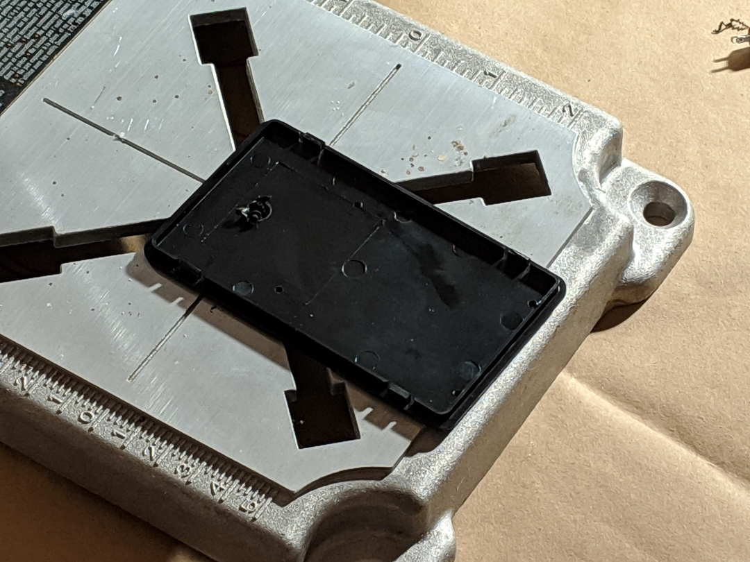
I’m using a dremel drill vise base here just so I have something to drill into, but in effect we’re going to drill (4) M2 sized holes to align with the mounting holes on our perfboard. I’m going to build into the enclosure lid as opposed to the base since it’s easier to work with. I’m also going to drill a 1/4" hole for my fancy button while we have all the drilling tools out.
Perfboard Build
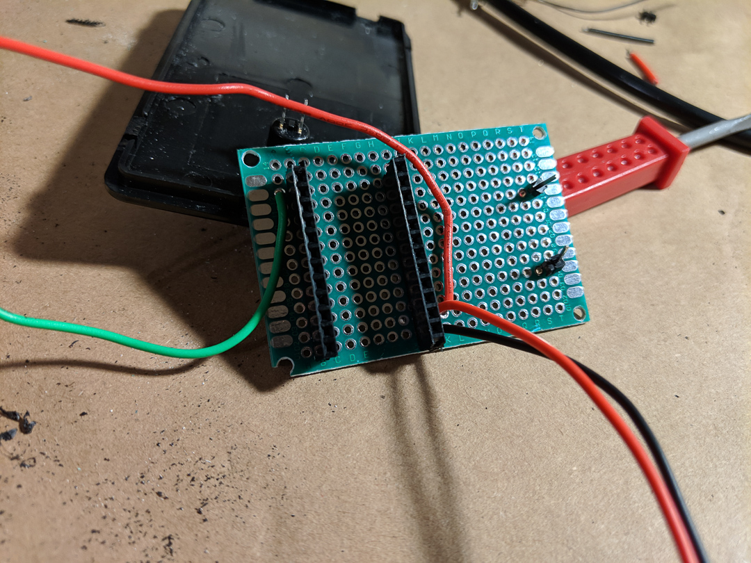
I’m using female headers so I can remove the Photon later if need be, and I’m going to use a couple male headers to help give my lipo circuit some better resistance to being plugged or unplugged. Note that if your female headers came in a longer row, you’ll need to snip them with some flush cutters and file down the end carefully.
I’m using some JST connectors to connect up my lipo cell, as well as my photon to the charger. The button is just going to be wired in using some solid core wires connected to the board.
Note that bridging across perfboard is kind of a pain. I used extra long wires to accomplish this but you might also use some spare component leads bent in a “u” shape.
Testing
Without the Photon inserted, plug in a charged lipo and test our voltage. Then we can unplug our lipo cell and plug in usb and double check that as well. Finally insert the photon, connect up a battery, and we should see the photon get all the way to a solid cyan light (meaning fully connected).
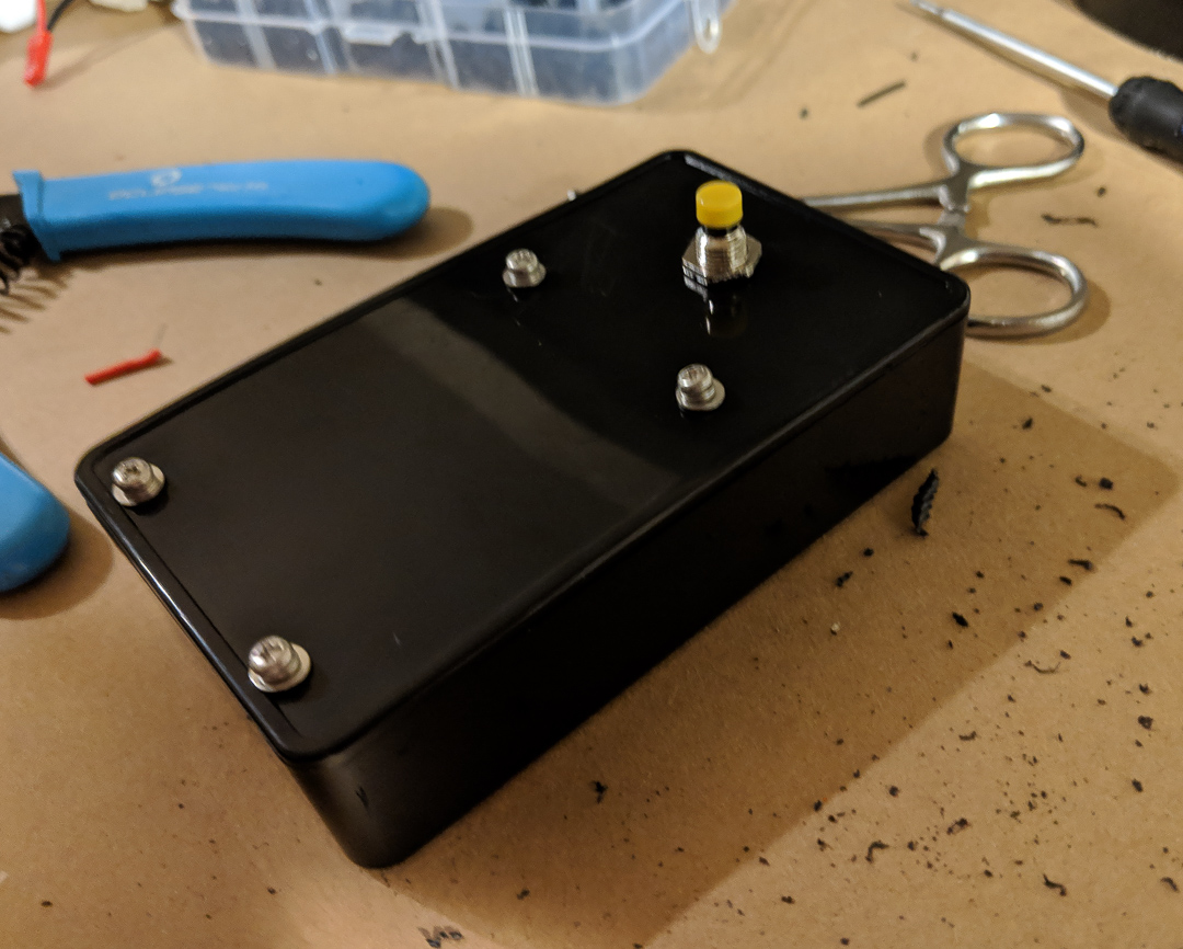
Assembly
If we want to use standoffs, we can insert those into our M2 sized holes earlier, or we can run screws from the outside in and use a nut to lock them into place. If you go the standoff route, you can secure them with a nut on the face side of the project enclosure, and even add a dab of glue to help add stability.
Either way we’re good to mount our perfboard to our standoffs (makeshift or otherwise) and use some tape to attach our lipo cell to our enclosure. Double check that we’re wired up to our button, and do a quick functionality test before we pop our enclosure closed.
Post build notes
So that process is what got me to V0, which to my surprise works pretty well. I do wish I had the foresight to add a power switch to it.
I could of left out the tp4056 circuit and instead used a Particle Xenon which has a built in Lipo charger. However when I designed this, I wasn’t sure if I would have that particular microcontroller on hand. Also they’re a bit more expensive, and I had a bunch of Photons floating around unused.
I initially tried to tap the drill holes. However, the project box isn’t really thick enough to allow sufficient threads.
I also initially used M3 screws and standoffs, but it turns out my perfboard was tapped for M2. Oops.
I couldn’t get my USB port close enough to the edge of the box to allow proper plugging. Nor have I found reasonably priced panel mount usb connectors.
My plan for v1 is to switch to getting a PCB printed. Working with a perfboard was painful, and I’d like to also get some LED indicators exposed on the top of the enclosure so you have an idea of the status. Also, a power switch wouldn’t be bad.